Proper Grounding for Safety and Lightning Protection
By Ken Pollock, WB3JOB and Jerry Silverstein, K3FKI
Introduction;
Proper grounding techniques are employed to alleviate a couple of potential problems, electrical safety and protection of equipment from lightning strikes. The question becomes “What is meant by a ground system?” The simple answer is a good connection to the earth to provide a low impedance path for unwanted currents or voltages that may be present. The NEC codes require grounding for protection from electrical shock and for lowering the effects of lightning discharge. This paper discusses grounding techniques that are utilized in the commercial field and how they may be used by the average “Ham” operator to effectively help protect his or her equipment.
Requirement for a good ground;
The requirement for a good ground is important for the safety of anyone using electrical equipment. The NEC 2005 Code (National Electrical Code) Article 250 requires that an electrical ground be low impedance and less than 25 Ohms (Section 250.56) while Section 810.51 of the NEC Code Book deals with the legal requirements for Amateur Radio Stations. The NEC Codes are written as minimum requirements and can be surpassed. For the standard electrical circuits in a home, two ground rods are normally employed. By the code, there must be at least two 8-foot ground rods located at least 6 feet apart (NEC section 250.53). In some locations, this will give a resistance of around 15-20 Ohms during normal conditions. This is fine until there is a drought or some other change in the moisture content of the soil when the resistance will skyrocket. Sometimes Mores’ Law will enter into the equation: “If a little is good, more is better, and too much is just right.” In other words, the number of ground rods can be increased to keep the impedance low.
With a good ground system, not only will the safety from electrical shock be improved, but also protection from unexpected electrical discharge to the connected electrical equipment will be provided. What a good ground WILL NOT provide is a lower SWR or a better antenna system! But, if done properly, noise MAY be reduced from the present poor installation with a properly designed and implemented system.
What can we use for ground rods?
Several devices may be used for the ground system to make electrical contact with the earth. Which type of device, is used, will be dependant on the conditions at the location that is to be grounded. For example, if an 8-foot ground rod cannot be driven in the earth due to the bedrock being only 4 feet down, then some other device must be used. A plate may be used or Chem.-rods employed, instead of a rod. The following are some of the common devices that are legal to be used for the grounding device.
Ground Rods
The most basic ground rod is a copper-coated 8-foot steel rod of at least 5/8” in diameter driven into the ground. A solid copper rod could be substituted or a rod of 10 feet could be used, but they cost more. The rod must be driven into the ground vertically or within 45 degrees of vertical. Notice that stainless steel ground rods are allowed but aluminum is not allowed! (Section 250.52, NEC Code book, 2005 revision)
Metal Underground Pipes
Metal under ground pipes may be used as long as they are not gas lines, they must maintain direct ground contact for at least 10 feet and not have any insulated sleeves, joints, or insulated sections within that 10 feet. Also, the electrical connection shall be within 5 feet of the wall or surface through which the pipe emerges but in no case be on the opposite side of a meter from the earth surface. Well casings may be used as long as they are at least 10 feet long and the connection is made below the earth surface.
Plates
A metal plate of steel or iron of at least 2 square feet in surface area and at least ¼ inch thick or plate electrodes of copper and other nonferrous conductors of at least .06 inch in thickness may be employed in place of a ground rod. The plates cannot be coated or protected in any way.
Chem.-rods
Basically these are sections of 1 ½” copper pipe that are formed in an “L” with 1/8” holes in the horizontal section. The pipes are filled with some sort of salt compound (such as copper sulphate) that will leach out of the pipe when there is moisture present. The salt then lowers the ground resistance appreciably. The problem with Chem.-rods is that they require maintenance and the salt has to be refilled periodically.
Ground Ring
A ground ring is a loop of #2 AWG bare or tinned wire buried 30” below the ground surface. This will give a large surface area and supply a good ground to a system. A ground ring must consist of at least 20 feet or more of #2 bare copper wire.
Notice that the Code allows the use of two or more of the ground electrodes but each device must be separated from the others by a minimum of 6 feet.
What About the Size of the Ground Wire?
The wire used to provide the grounding between the electrodes should be as large as possible. The minimum size allowed is #6 AWG (with exceptions) and must be run between all electrodes in a continuous run. If there are to be any breaks, they have to be connected by “cad-welding”. The wire may be connected to the ground electrodes by means of cad welding or by a clamp. Larger wire is used for several reasons, first of all, the larger the wire, the lower the resistance and the lower the damage in case of a lightning strike. Next, larger wire has much lower inductance and this is really important with lightning, as the change of current versus time (dV/dT) is very high and for a small period of time, the ground doesn’t even appear to be connected! An inductor opposes the change of current and a large voltage will appear across an inductor until current starts to flow due to self-inductance. It is better for all the right reasons to have the lowest inductance.
If at all possible, use a stranded wire with fine strands. A good example is welding wire. It is rather expensive but it is designed to give a large current flow with low losses and low inductance. Tinned entrance wire also works fine but isn’t as flexible, but is cheaper and more readily available. This wire is even available at Lowe’s and Home Depot.
The wire that connects the ground rods together is normally referred to as the bonding conductor and must be at least #6 or larger and aluminum is allowed but must be a minimum of #4 gage. The connections to the copper ground device must be protected by use of a corrosion inhibitor such as “NoAlOx” or similar substance.
Installing the Ground Bed
The ground rods and the bonding wire form what is called the “ground bed” and is the actual ground system to shunt undesirable currents to earth ground. The first thing to consider is where the protected devices are physically located. For example, to protect a Ham Shack, the ground lead from the room to the ground bed should be as short and direct as possible. The ground bed should provide protection to the radio equipment, the tower or antenna support structure, the electrical system, and the buildings containing the system. Refer to Figure 1 for the explanation of the system.
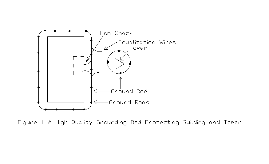
A ground ring is to be installed around the building containing the radio equipment and a second ring is placed around the tower. A series of ground rods are to be installed 8 to 10 feet apart in the ground ring. The ground ring will be located about 3 feet away from the building and 6 feet from the tower. The ground ring around the tower will be connected to the ground ring surrounding the building by use of equalizer wires. The purpose of this arrangement is to equalize voltages that would be present in the earth due to sheet resistance, should a lightning strike occur nearby. Although this plan appears to be “over-kill”, one must realize that this is the ideal design as it performs the following functions:
- It equalizes the voltages in the earth surrounding the equipment (called the Earth Gradient).
- It guarantees that the resistance of the ground bed will be less than 25 Ohms.
- It will provide a convenient system to allow all of the various grounds to be bonded together (NEC Section 250.50 and Section 250.53).
This system effectively solves all of these problems and will allow for a reliable ground system for the services required.
Now, from a practical standpoint, most Hams cannot install a system this good, due to driveways, trees and shrubs, etc., getting in the way. Instead of having the ground ring encircle the house, one might opt to have just the part of the ground ring across the back of the house or building or maybe the back and just one side. This is fine as it is definitely better than the ground installed by most electricians for the electrical safety of the power mains and for inspection. A ring around the tower is a must and there should be two ground cables coming from each leg of the tower to the ground ring. Make all bends of the ground wire as sweeping bends to minimize inductance and position the wires such that they point away from each other when making the connection to the grounding ring.
The ground rods have to be a full 8 feet long and driven completely into the ground, so that their tops are 4 to 8 inches below the top of the ground or ground cover. The bonding wire may be clamped onto the ground rods with bronze clamps. The bonding wires have to be buried at least 18 inches below the ground cover.
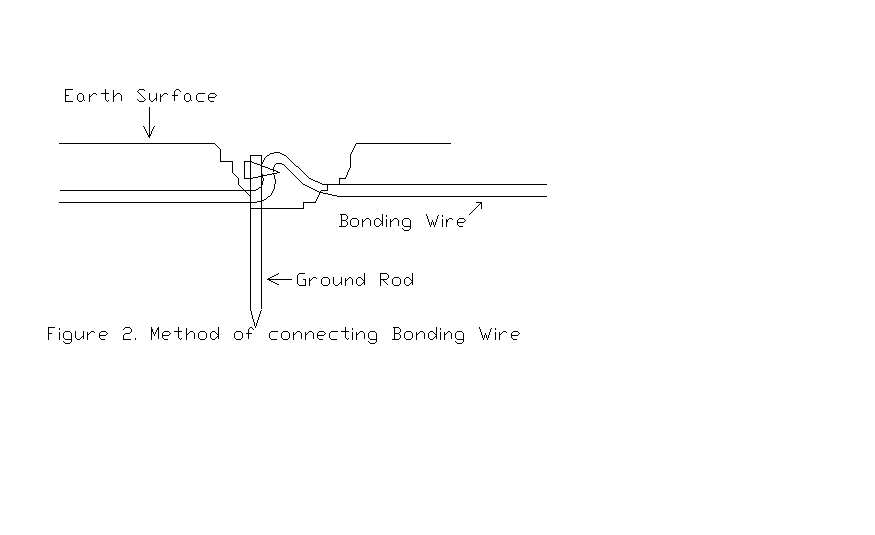
Refer to Figure 2. in the following explanation. Notice that the tops of the ground rods are below the surface of the earth and that the ground wire is clamped to the ground rod but is not cut or broken. Otherwise the bonding would be done by Cad-welding in order to keep the resistance as low as possible and to provide a reliable connection. Also notice that the bonding wire is not insulated, as the surface of the wire, which is in contact with the soil, will aid in lowering the resistance of the grounding system. Therefore, the cable should be tinned copper, etc.
One word of caution; if aluminum wire were to be used for the bonding cable, a chemical reaction with the copper rod would take place and the connection would corrode very quickly. Some type of protection, such as the use of “NoAlOx”, or some other type form of corrosion prevention, grease, or coating would be required. Also, periodic or annual inspection would have to be performed to insure connection integrity.
This would require one to dig up the top of the ground rod or to install inspection ports, to allow the connection of the bonding wire to the ground rod to be examined and tightened if necessary.
The trick is to design the ground system to be more than just adequate, if it is expected to be reliable when the need arises. Putting things in perspective, design the ground as if one was expecting to be hit by lightning or having to handle a large current to ground, as when a transformer shorts its primary to ground! If this advice is followed, everything will be ready in case you do get hit and the damage will be minimal. Poor ground systems can actually cause more damage than they prevent!
One-Point Grounding
The purpose of one-point grounding is to prevent any electrical discharges or currents from flowing from one piece of equipment through another and causing damage. In simple terms, this is bringing all of the ground connections to one common point that is grounded. Lightning caused currents will flow from a piece of equipment to the grounded point and then to ground.
Industrial and commercial users spend a lot of money on grounding plates. One such plate is made of solid ¼ inch copper, about 5 inches tall, and 20 inches long. This plate has a series of holes drilled in it for 3/8 inch or ½ inch bolts to allow the various ground wires to be attached by means of crimp-connectors. The plate is insulated from the building, etc and is used for all of the ground connects of just the electronic equipment. The electrical equipment is grounded through the electrical service panel to a ground that is bonded to the ground bed but not through this plate. This forms what is called a quiet ground.
A lower cost option would be to mount a 1-inch piece of copper water pipe at the back of the bench. Make sure that the pipe is insulated from the bench and can be reached. In a commercial application, there are normally two #2 AWG wires that would be connecting the ground plate to the ground bed. For most amateur work, a single ground wire of #6 AWG or larger would suffice.
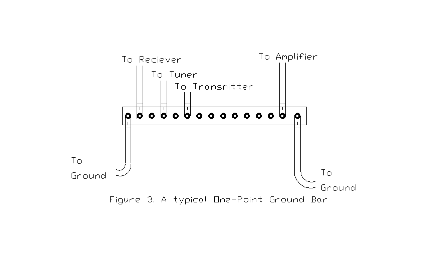
Drill holes through the pipe and use crimp-connectors on the wires coming from the equipment that is to be connected. Do not connect a ground from one piece of equipment to the next! Run a separate ground for each piece of equipment and securely bolt each wire to the one-point ground bar. Use one hole for one terminal and one piece of equipment and the equipment will be grounded but yet separated so that any currents will not flow from one piece to the next. Make the ground wires running from each piece of equipment as short as possible and avoid any right-angle bends that would increase the inductance of the wire.
Refer to Figure 3 on the next page. This is how a typical one-point ground bar would be organized. You will notice that a ground lead is supplied for each piece of equipment. Use as large of a wire gage that is possible and short enough to just make the connection while using a flexible wire, so the wire can be moved. Typically #2 green colored welding wire is used for this purpose.
DO NOT RELY ON THE OUTER SHIELD OF THE INTERCONNECTING COAX TO SUPPLY A GROUND CONNECTION AS ANY CURRENTS FLOWING ON THE SHIELD CAN INDUCE VOLTAGES ONTO THE CENTER CONDUCTOR AND DAMAGE SENSITIVE CIRCUITS, DUE TO MAGNETIC COUPLING! Sorry to say that this is a major cause of damage to radio equipment. Rely on the coax to carry RF signals and the ground wires to protect the equipment.
Grounding of Coaxial Cables
The coaxial cables should be grounded at the minimum of at least one point; that being at a location before the coax comes into the ham shack. It’s not wise to bring any lightning into the building, stop it before it comes into the building. A simple method to do this is by mounting double-female connectors on a sheet of metal (aluminum, copper, even a piece of circuit board works well for this) that is then grounded to the ground bed. In this case, a ground wire would be run from the metal plate directly to the ground bed… not the one-point ground.
This also allows one to install lightning protection devices such as “Transi-Traps”, “Trans-Sorbs”, or any one of a number of other commercial devices available on the market today. There are a number of manufacturers that have a wide variety of products readily available.
Another way of grounding coaxial cables is by carefully cutting the outer covering and exposing the shield underneath. The ground lead is then connected to the shield by either a clamp or by soldering the ground lead directly to the shield. The grounds from each of the coax leads would then be taken to a second one-point ground bar (not the ground bar in the ham shack) and the ground bar is directly grounded to the round bed. If a tower is employed, the same grounding arrangement would be accomplished by grounding the shield by use of ground leads to a ground bar mounted on, but insulated, from the tower. This ground bar is then grounded to the ground ring that runs around the tower base.
Although this type of grounding is a lot of work, the benefits are well worth the effort. There is something to be said about having a reliable ground system that doesn’t let you know that you got struck by lightning and the equipment seems to keep on running!
Odds and Ends
There are a couple of small but important items that should be attended to in order to prevent damage from “sneak paths”. First of all, these sneak paths come from such wiring as the power supply, audio cables, peripheral device wiring, and so forth. To prevent lightning damage due to these connections, all leads between two devices should be protected by running the wires through a ferrite torroidal core with about 3 to 5 turns in the coil. This will increase the inductance in the wiring so that any static discharge will go to the ground bar first by way of the ground lead and be drained off, instead of flowing between two devices such as a power supply to the transceiver. Each cable or lead should have its own core for protection.
The type of material in the core should be ferrite and the size of the core should be large enough so that the leads will pass through it easily. Almost any of the ones available at hamfests will work fine for our purposes. The exact value of inductance that will be obtained, when the leads are wrapped through the core, is not important. What is important is that the coil and the core introduce some inductance so that the cables have a high enough impedance so that the sudden and fast rise of a voltage or current change is effectively choked off thus preventing currents from flowing.
Another thing to do is to insulate everything from ground and rely on the ground leads to provide the grounding. This means that metal desks be insulated from the concrete floor, etc. This removes another possible path that may cause damage.
Finally, when the station is not being used, ground the antenna center terminals so that the RF connections to the radios are shorted. Most Hams do this already but it is important to reinforce this advice.
Summary
Do these measures work? In Wilkinsburg, there is a microwave location where these measures have been instituted. This site usually takes direct lightning hits about 4 times per year. Before these measures were installed, one could expect about 4 or 5 circuit cards, two or three modems, the utility electric meter, and other devices to be taken out with each strike. Last year (2005) there were 5 different strikes and the only damage was that a computer had to be reset and rebooted.
Pictures
The following are pictures taken at a microwave site in order to illustrate that which was just discussed. First of all, how would we protect the following lightning rod?
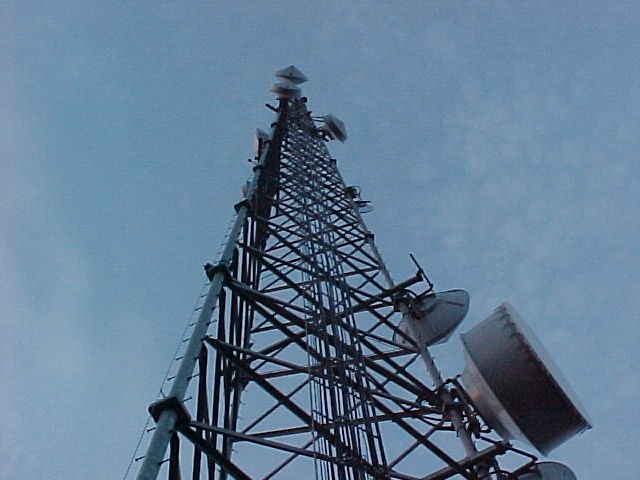
This is a picture of a 250 foot, self-supporting tower located in Wilkinsburg. The highest item on the tower is at the top and is a 4-foot long lightning rod. Below that is the beacon assembly and then below that are the various antennas. Notice that there are two-way antennas as well as the microwave dishes.
To what are the antennas connected?
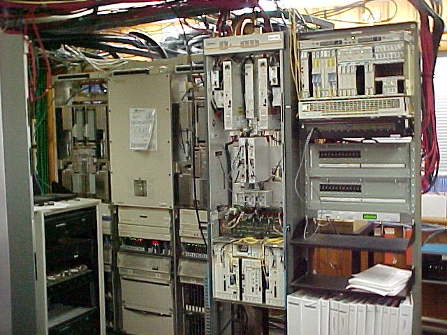
This is a small portion of the equipment at the base of the tower. There are microwave transmitters, channel banks, two-way radios and other radio equipment shown. Although it is hard to see in this picture, look closely and you should be able to locate the 4/0 grounding wires (they are green colored and at the upper left of the picture). Notice that the power supply wires (the red and the black wires at the right side of the picture) are made of 2/0 welding cable and are run separately from the signal wires. The wave-guide and the coaxial cables for the input to the receivers are run separately and cross at right angles to the signal wires. This keeps any static discharge on the antenna side and out of the signal paths.
The yellow wires are really fiber-optic cables as they are not electrically conductive and they are capable of handling the high-speed signals that are being processed. This station handles a traffic load of three OS3 signals each direction that is a signal bandwidth of above 45 MHz. If you think you have seen high speed Internet, you haven’t seen anything, yet! This “node” handles 1024 telephone calls, 128 different T1 internet lines, the signaling and control of 512 control points for the SCADA system, and the measurements taken along 428 miles of interstate pipeline, simultaneously
The following picture shows that one-point grounding is employed with each rack of equipment having its own #4/0 ground cable going to a common ground.
This ground block has all of the cables bolted to it and all point towards the earth ground connection. This reduces any inductance and the high impedance that is offered to a static discharge. By locating the one-point ground away from the equipment, as is shown, electrical discharge that would normally flow from one piece of equipment to the next, would now have to flow to the grounding block and then back to the other piece of equipment. Since this is a high impedance path, (as compared to ground) the discharge flows to earth ground. Wires between the racks of equipment have the interconnecting cables fed through a ferrite core to prevent conduction along that route.
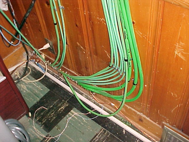
Next, all of the cabling from the tower is grounded by an insulated grounding block on the outside of the building. Here we can see individual wave-guides and coaxial cables as they are grounded.
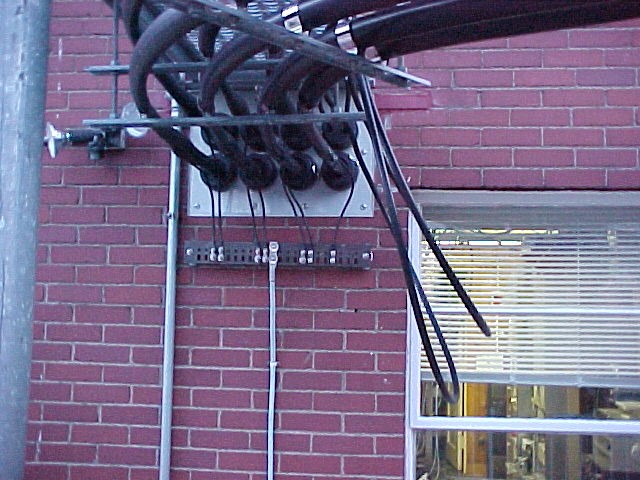
The heavy lead coming from the center of the copper grounding block is taken directly to the earth ground and it connects at the same point as the ground from inside the building.
Yes you are seeing right, the ground lead is a coated, silvered lead and all bends are made with sweeping bends to keep the inductance as low as possible. The two Heliax leads have a loop in them serving a dual purpose. First of all, the loops act as rain drips. Second, the additional inductance that results from this loop stops lightning from traveling into the building.
Each of the tower legs have two ground leads coming from them. Notice that the bends in the loops are, once again, sweeping loops to minimize inductance. These ground leads are made from #4/0 welding cable and are cad-welded to the tower plates.
NEVER CAD-WELD THE TOWER LEGS AS THIS WILL CAUSE INTERNAL CORROSION AND WEAKEN THE STEEL!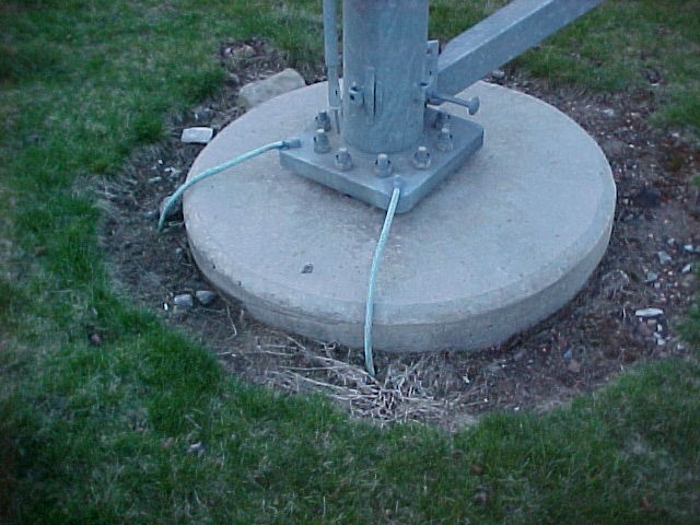
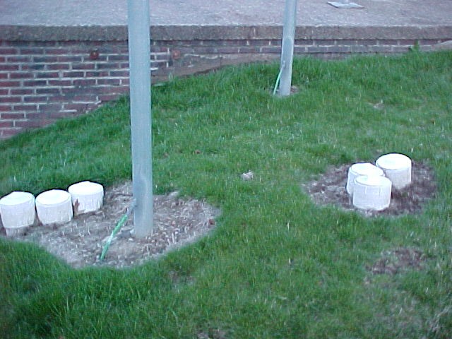
The final picture illustrates the method used to allow for inspection of the welds on the ground cable, the bonding cable and the ground-rods. From a commercial standpoint, it is imperative that the ground resistance has to be measured on an annual basis and that the bonds have to be periodically inspected. In order to do this, inspection ports are provided so that these inspections may be performed. The inspection ports are made from pieces of 4” PVC pipe and have caps that may be removed. It’s simple but effective!
The resistance of the ground-rods, the bonding wires, etc, are measured every year and have been consistently under 1 Ohm each time. Compare this to the nominal resistance of the standard ground employed for the average home as being from 10 to 20 Ohms.